Flexible Solar Panels
In a traditional rigid printed circuit board the base material is woven fiberglass impregnated with epoxy resin. This cured epoxy is what gives the boards their rigidity. Rigid PCBs are great for applications that do not require much movement of the boards. However, for a more dynamic application like an electronic instrument or mobile phone that needs to flex during use, then a flex circuit is the better option.
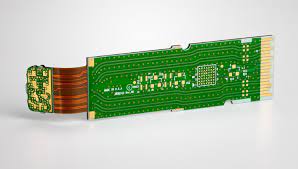
A flex PCB is made of a flexible polymer substrate film, which is often referred to as Kapton, that can be shaped into the shape of a device. It is typically used as a connector, cable replacement or as the main substrate for components and circuits.
Printed circuit boards can have many different configurations and construction techniques, and the materials that are used vary. But the most common type of flex PCB is made from a polyimide (PI) film, also known as Kapton, that has been coated with a layer of conductive copper. Conductive layers are then etched on the PI film and covered with a layer of non-conductive coverlay to protect them from moisture and environmental conditions.
The advantages of using a flex pcb board include the ability to reduce weight in a product by replacing cables and wire harnesses. The design flexibility of a flex PCB can allow for new features and improved connectivity. It is possible to achieve significant weight reductions of up to 75% compared with a standard rigid-flex board.
Flex PCBs for Flexible Solar Panels
A major disadvantage of using a flex circuit is that the flexible material can be easily damaged due to moisture, chemicals, and harsh environments. Repeated bending and flexing can cause material fatigue, which can result in electrical failures. Therefore, the use of a flex PCB requires careful design and manufacturing to ensure its durability and long life.
Another challenge with using a flex circuit is that it can be difficult to repair, since the tracks on each layer are very close together. This can be overcome by using a high-quality manufacturing process that provides good mechanical stability during the lamination and assembly. The use of a high-grade copper foil can also increase the durability and reliability of a flex circuit.
In addition, it is recommended to use rounded corners on the pads of the flex PCB in areas where it is expected/designed to be bended as this will provide a better tear resistance than sharp edges. This will also help prevent the copper from cracking during flexing.
Altium Designer has a wide range of advanced CAD features and automated drawing tools that can be used for a wide variety of complex electronics projects. To get started with a free trial, visit the Altium website.
A flex pcb is a multi-layer printed circuit board, just like its rigid counterpart. However, unlike rigid PCBs, it uses a polyester or polyimide film that can be as thin as 12 to 120 microns. Conductive material traces are then etched on these layers and protected with various surface finishes.