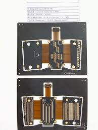
PCB Flex Circuits
The ability to easily bend and flex circuits to meet the needs of a design has made them popular in the electronics industry. Often replacing wire harnesses and ribbon connectors, they are capable of reducing assembly steps as well as the potential for errors during connection. They can also help to lower overall product weight by allowing designers to incorporate more components in a small space, minimizing the need for hefty cables and wiring.
The primary component of any pcb flex is the base material that provides most of its physical and electrical characteristics. Typically, it is a flexible polymer film, such as a polyimide. The copper conductor is printed on top of the base film, and a layer of dielectric insulates it. The conductive copper is then covered with a solderable surface coating, such as Electroless Nickel Immersion Gold (ENIG), that acts as a barrier between the copper and the surrounding base material.
As a general rule, the number of layers in a flex circuit will determine how much bending it can take. The higher the number of layers, the more flex it can handle. The more rigid the base material, the less flex it can take. There are some exceptions, however. For example, woven fiberglass impregnated in epoxy resins are sometimes used for organic rigid-flex PCBs and provide a reasonable amount of elasticity.
How PCB Flex Circuits Can Be Used in Renewable Energy Systems
When selecting a flex circuit material, it’s important to consider factors like temperature, chemical exposure, shock and vibration. Getting this information early on in the project can help to ensure that the flex circuit is built to withstand harsh environments. It can also help to model the mechanical performance of the product, determining things like the minimum allowed bending radius and other factors that could be detrimental.
In addition to choosing the right materials for a flex circuit, it’s also important to choose the correct surface finish. This serves two important purposes: it prevents the copper from oxidizing and makes it easy to solder. A popular choice is Electroless Nickel Immersion Gold (ENIG). It’s also possible to add pad fillets, which improve etch yield and material strength. These are appropriate when the pad diameter is larger than the connecting strand width.
Another important consideration is tracing width. For example, if you’re designing a flex circuit for high-speed signal routing, it might be best to use wide traces. This will decrease the resistance to flexing and improve signal timing. Similarly, it’s common to use narrow traces for low-speed signals.
The ability to quickly and easily change the shape of a flex circuit is especially useful for renewable energy applications. Solar panel arrays in particular can require a lot of flexibility to allow for tight routing within a small space, and flex circuits are an ideal solution. Moreover, the flexibility of these boards can improve thermal efficiency and reduce overall product weight by replacing bulky wiring harnesses with their lighter, more compact counterparts. In fact, many of the world’s most advanced solar panels are manufactured on a flex circuit.